ABOUT BUILDING

8%

Review and Herald Publishing Company · Battle Creek, Mich. · Jul 13, 1899

FromThe Youth’s Instructor, Vol. 47, No. 28.

Read the full edition

ABOUT BUILDING.

WELL, boys, perhaps some of you begin to think it is about time for me to say something in regard to building. If you will give strict attention to what I now write and illustrate to you, I will teach you how to plan and build a cottage. It is important to know how to plan and draft out a piece of work to a scale before you build it; then you can lay your rule on your plan, and get accurate measurements for the work, and thus avoid making mistakes.
You will need a few tools with which to do your drawing. First, you should have a drawing-board. Get a good pine board about fifteen inches wide; or, if a board of that width is not easily obtained, glue two pieces together. It should be about twenty inches long, and of equal width. Dress both sides smooth, and make the ends as nearly square as possible. Get drafting-tacks, or pins, to hold your paper to the board. Next you want a T-square, which is made of cherry, maple, or some other finely grained wood. This tool costs but a trifle. It would be well to purchase a set of high-school mathematical instruments, which can be procured for about $1.50. If you can not get this set, use a pair of common dividers. Then you want an architect’s drafting-scale; or, if you have a good brass bound two-foot rule, you will find, upon the inside, four scales,—a one-inch, three-fourths-inch, one-half-inch, and one-fourth-inch, each divided into twelfths. You can draft by these scales until you can procure something better.
A word in regard to the use of scales will be of value here. A floor plan or the elevation of a house is usually drawn on a scale of four feet to the inch; but where the building is large, requiring a sheet of paper of a size inconvenient to use, it is sometimes drawn one eighth of an inch. But the prettiest scale to work to in drawing out details of work is one and one-half inches to the foot, which gives you one eighth of an inch for one inch in the scale. But I will speak further of this another time.
Whatever the building you construct, you should see it in your mind as complete as if it already existed before your eyes. When our grandfathers were boys, people were ignorant of the methods of laying out a frame for a large building, but would lay out a stick at a time, and fit it together by what they called the “scribe rule.”
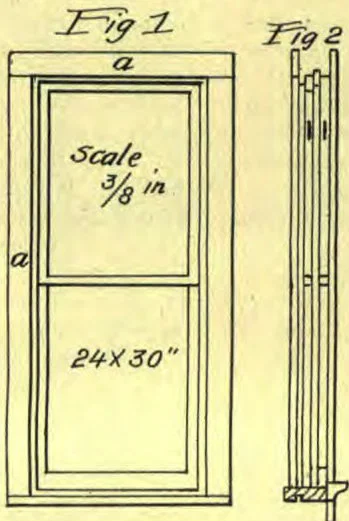
I want you to learn the technical names of the different parts of a house, so that you can work understandingly, after which we will together draw the plans for a nice cottage, and build it, step by step, until it is completed. In this lesson I will give a few illustrations of some parts of a house. Fig. 1 represents a window frame complete, such as we would need for a cottage. The size of the glass is 24 x 30 inches, with check-sash.
Fig. 2 is a side section of the frame, showing the stops and casings, drawn on three eighths-inch scale.
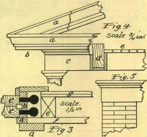
In Fig. 3 we have a section of the side of the frame drawn upon a scale of one and one-half inches to the foot. This scale is so large that the different parts can be lettered, so that when they are mentioned again, you will easily recall them. As represented, a is the face casing, usually four inches wide, one and one-eighth inches thick. This is the outside; the top casing measures the same. At b is shown the jamb, on which the sash slides; at c, c, the window-sash. The jamb is about five inches wide. It has a groove at b three eighths of an inch deep, one-half inch wide for the check-stop between the sash. At d is the blind stop, which projects one-half inch beyond the face casing, and is nailed on before the face casing is attached. You will observe two pulleys through the jamb, with their weights. Each weight should equal about half the weight of the sash and glass combined. There is a pocket in the jamb to put the weights through, which will be explained later. At e is the stud, 2 x 4 inches, which is set two and one-fourth inches from the jamb, thus leaving room for the weights to play in raising and lowering the sash. You will see at f the sheeting upon the outside of the studding, of common, mill-dressed lumber, covered with building-paper, and at g, the lath and plaster.
In Fig. 4 we have a section of veranda cornice, drawn upon a scale of three fourths of an inch to the foot. The crown-mold is shown at a, a. It is thus named because it is the crowning member of the cornice. The board underneath the crown-mold, at b, is the plancher. Under the plancher, at c, is the bed-mold. At d is shown a section of the box cut through that which runs over the columns. This is called a soffit. Below the soffit is shown the upper end of a column. At e may be seen the matched ceiling over the veranda.
Fig. 5 represents the end of the veranda floor, with casing and molding under the floor, called the nosing.
As I have already said, I hope you will give strict attention to this lesson, in order that you may keep pace with the instruction in cottage-building. W. K. LOUGHBOROUGH.