Perhaps there is nothing in the line of wood-work that would interest the amateur more than wood-turning; for there are many things that can be made by this method of workmanship, such as household utensils, handles to tools, boxes, brackets, and useful trinkets of various sorts. When I was thirteen years old, I had a turning-lathe, on which I did a great deal of work. You may ask, “Of what use would be a turning-lathe without steam- or water-power?” —Well, there is a great deal of useful power in the leg and foot, if rightly applied. For a small outlay, you can make a lathe to run by foot-power.
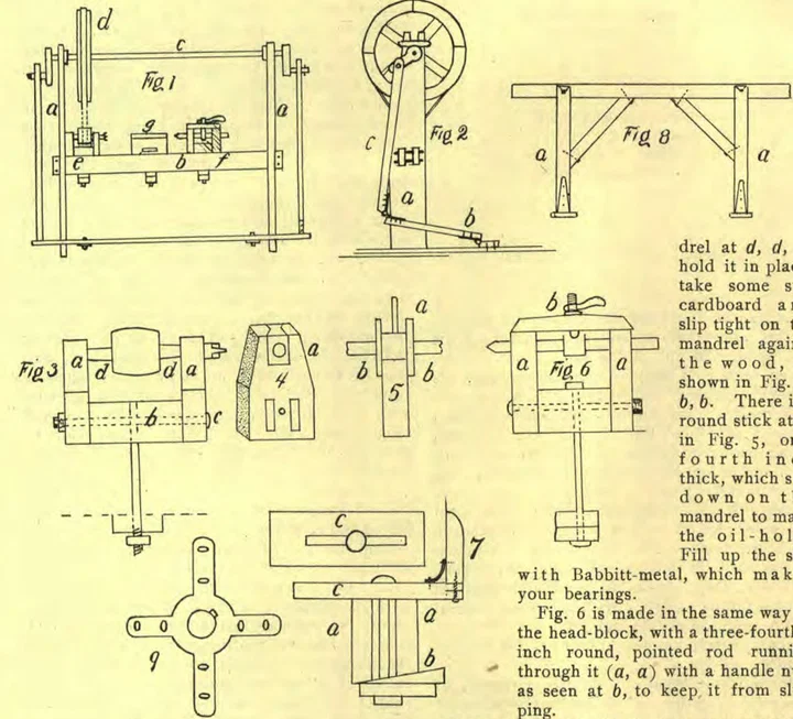
In this lesson I will illustrate some instruction about making such a lathe. In Fig. 1 you will see a lathe set up, like one I am building for myself. First, a, a, are two planks six feet long, twelve inches wide, and two inches thick. Beginning three feet from the bottom, these taper back to eight inches in width at the top, thus throwing the wheel farther back. Two planks six inches wide are shown at b. The top of these should be three feet from the floor. There are two of these, two inches apart, mortised through the two upright planks. Make the mortise five inches long, leaving a shoulder half an inch high on each edge of the six-inch planks; then insert two half-inch pins outside the upright plank, as seen in illustration, at the ends of plank, b, and in c, Fig. 2.
The main shaft, c, Fig. 1, is of one-inch round, rolled iron, seven feet long. Attached to it is the driving-wheel, d. To make the wheel, use two planks five inches wide, three feet long, one and three-fourths inches thick, halved together in the center. Bore one-inch hole through the center. Make the rim of two thicknesses of one and three-fourths-inch pine or whitewood plank, screwed or nailed together. Have cross-pieces one inch thick run through them. Break joints in the rim when you put them together. You should have a cast-iron piece called a spider for the shaft to go through. This is bolted on the arms of the wheel. See Fig. 5.
At e, Fig. 1, you will see what is called the head-block, in which are the shaft, called the mandrel, and the pulley, which hold in place the piece to be turned. The same is shown in Fig. 3. The tail-block is shown at f, and the rest, upon which to support your chisel, at g.
Upon each end of the shaft, c, is a crank with two pieces of hard wood running down to the treadle. (I will give you a picture of these cranks with the other patterns.)
In Fig. 2 you will have an end view of the upright plank, with wheel, crank, and rod, which should be about two inches wide in the center, and one and three-fourths inches at the ends. Attach these rods with T hinges, as seen at a, and at b, which is screwed to the floor.
In making the head-block (see Fig. 3), a, a are one and three-fourths inches thick, nine inches high, six inches wide, and taper to three and one-half inches at the top. In this figure, b is a piece of scantling three and one-half inches square, with a double tenon on each end, half an inch long, to go into mortises, shown in Fig. 4. These are held together with a bolt running through at c. Then the iron called a mandrel is centered in the place where it belongs. After putting something under the mandrel at d, d, to hold it in place, take some stiff cardboard and slip tight on the mandrel against the wood, as shown in Fig. 5, b, b. There is a round stick at a, in Fig. 5, one-fourth inch thick, which sets down on the mandrel to make the oil-hole. Fill up the slot with Babbitt-metal, which makes your bearings.
Fig. 6 is made in the same way as the head-block, with a three-fourths-inch round, pointed rod running through it (a, a) with a handle nut, as seen at b, to keep it from slipping.
In the next article I will give you description of Fig. 7, the patterns of casting needed for the lathe, with the crank attachments.
W. K. LOUGHBOROUGH.