How to Make an Electromagnetic Coil That Is Inexpensive
By Uthai Vincent Wilcox
Leyden jar
CONSTRUCTING an electromagnetic coil is quite simple, in spite of the complicated appearance of one. The simple making of a coil will teach you many things about electricity, and besides there is a great deal of amusement that you can obtain from one by giving your friends shocks, or you can have a steady current, similar to that given by the nurse with her electrical medical battery. The shocks will not be such strenuous, hard ones as you may get from the Leyden jar, or from a plate machine; but a prickly, tingling sensation, as when your arm goes to sleep. And then you can control the current, making it so weak as to be scarcely felt, or strong enough for two persons.
FIGURE 1
FIGURE 2.
The most expensive of the materials used are the insulated wire and the platinum, and all that is required of these can be bought for about a dollar, or perhaps less, according to where you live.
The following materials will be necessary in the coil described: 200 feet of No. 36 and 11 feet of No. 20, insulated copper wire; 15 feet of ordinary annealed iron wire, such as is sometimes called stovepipe or telephone wire; a small piece of platinum wire, about ¼ of an inch long; a piece of platinum foil, ¼ of an inch square, and a few pieces of brass, which you can pick up anywhere.
The coil consists of seven parts: the core, primary coil, reel, secondary coil, regulator, contact breaker, and base.
FIGURE 4.
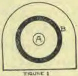
To make the core, get a piece of hard wood half an inch thick, cut off a piece about 1¾ inches square, and round off the two corners so that it will resemble Fig. 1. This is called the head. Through the center of this block, bore a hole ¼ of an inch in diameter. (See A, Fig. 1.) In this, place as many pieces of annealed iron wire, five inches long, as possible, making them project on one side ¼ of an inch; wedge them tight with a soft iron nail, as in D, Fig. 2. This bundle of wire forms the core, and on it is wound the primary coil, composed of No. 20 insulated copper wire.
Both ends of the wire in this, and also in the secondary coil, should be left projecting several inches, for the purpose of making connections, as explained later.
Begin your winding close up to the head, and wind carefully over the core up to the other end, and then back again, so as to form two layers of wire. Cover the coil with a strip of heavy brown paper, and carefully coat it with a thin layer of varnish made of gum shellac dissolved in alcohol.
The reel consists of a paper tube with a head firmly fixed at each end, which should be of the same shape and size as used on the primary coil. One should be ⅛ and the other ½ of an inch thick. Through the center of each bore a hole 1 inch in diameter. You can make the tube by winding brown paper around a stick or cylinder ¾ inch in diameter; the paper should be gummed or glued on one side as you wind. After it is dry, remove from stick, and you should have a tube 5 inches long and 1 inch in diameter. Now glue the heads on.
The secondary coil is wound on the reel. It is made of silk-covered No. 36 copper wire. When you handle this wire, be very careful to avoid breaks or kinks. Leave the ends projecting for making connections. The winding should be up close to the thick head of the reel, and continue until you have wound on 200 feet of wire; finish at the same end at which you began. You may cover this with either paper, leather, or velvet, as preferred.
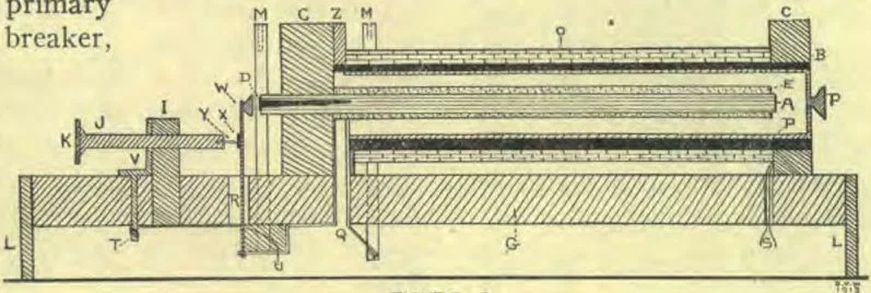
Now glue the thin head of the reel solidly to the head of the primary coil, so that the latter will lie within the paper tube of the former, and the terminals, or two ends, of the primary coil will pass between the two heads, as shown at Q, Fig. 2, Z being the head of the reel, and G the head of the primary coil.
The regulator is a copper or brass tube, equal in length to the paper cylinder of the reel, within which it should slide easily. On one end is a piece of metal with a knob (F) to be used for a handle, to pull the tube out, and to increase the strength of the current.
The contact breaker is of two parts—a vibrator and a platinum screw. The former is composed of the spring (H, Fig. 2), ¼ of an inch wide, made of steel or brass. The lower end is fastened to a small piece of wood or metal (U) placed beneath the baseboard, near a hole through which the vibrator rises vertically, so that the face of the iron clapper (W), fastened at the upper end of the spring, shall be directly in front of the projecting end of the core and about 1-16 of an inch from it. A short distance from the vibrator, place a wooden pillar (I), to which fasten an L-shaped piece of brass (V). Through this pillar pass the platinum screw (J), made of an ordinary13brass screw, on the head of which is soldered a one-cent piece (K), and the point of which is armed with a piece of No. 18 platinum wire (Y), from which the screw receives its name. This platinum wire comes in contact with a piece of sheet platinum (X) soldered on the spring of the vibrator, a little below the clapper.
The base may be made of any well-seasoned wood. Make it 8 inches long, 3 inches wide, and 1 inch deep. Place the coil horizontally at one end, and fasten with screw driven up from below into the heads. Make holes for the primary and secondary wires and the vibrator to pass through. The contact breaker is fastened in its place at the proper end of the coil.
At this end two binding posts (M and M′) for connections with the battery are necessary. These may be easily made by taking a piece of large brass wire, or a screw, and drilling a hole in the top, as indicated by the dotted lines. The lower ends should project beneath the baseboard. Two similar posts (N and N′, Fig. 3) are required on the opposite side of the coil.
The connections are all made beneath the baseboard. Figure 3 represents the appearance of the underside of the coil when all parts are connected. Primary wires (Q) are joined with the vibrator (H), the other with the post (M). The post (M) is connected by a piece of wire with the screw (T), which is screwed through the piece of brass (V, Fig. 2). The secondary wire (S) is connected with the posts (N and N′), which are the binding posts for connecting the electrodes with the coil.
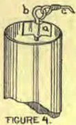
For the handle of the electrodes, make two cylinders of tin, 1 inch in diameter and 4 inches long. Solder a loop of tin (a, Fig. 4) on the inside at one end, into which fit eyes (b), fastened at one end of the conducting cord (c), so that they will jam tight. Connections with the battery and posts (M and M′) may be made in a similar way, by making the eyes fit into the holes drilled into the top of the posts.
Almost any battery may be used with the coil. To use the coil, see that all connections with the battery are properly made, and then turn the platinum screw slowly until the point just touches the vibrator, or until the spring begins to vibrate, then turn it back and forth until the buzzing sound made by the vibrator becomes steady. When all is ready, grasp the handles of the electrodes firmly, one in each hand, and pull out the regulating tube until a current as strong as desired is obtained.
The illustrations are made to be used as working drawings if desired. In all of them the same letter is used to refer to the same thing.
A. The core.
B. Paper tube of the reel.
C and C′ and Z. Heads of primary coil and reel.
D. Soft iron nail used as wedge for core.
E. Primary coil.
F. Knob for moving regulator P.
G. Baseboard.
H. Spring of vibrator (thickness exaggerated).
I. Pillar supporting platinum screw.
J. Platinum screw.
K. One-cent piece fastened to head of screw.
L. Legs supporting baseboard.
M and M′. Binding posts for batteries.
N and N′. Binding posts for electrodes.
O. Secondary coils.
P. Regulating tube.
Q. Ends of wire of primary coil.
R. Hole in baseboard for vibrator to pass through.
S. Ends of wire of secondary coil.
T. Screw for holding V in place.
U. Block supporting vibrator.
V. L-shaped piece of brass for making connection with platinum screw and the post M.
W. Clapper to vibrator.
X. Platinum foil on vibrator.
Y. Platinum wire in front of screw J.
Fig. 1. Shows the shape of the heads.
Fig. 2. Shows a section through length of coil.
Fig. 3. Shows under side of baseboard.
Fig. 4. End of handle to electrode, showing how connection is made with conducting rod.